The elementary circuit: A battery and a resistor
We'll begin our study of circuits with the most basic of all circuits, a battery and resistor connected in series. While this circuit isn't very practically useful, you'll find that you'll be using it often as you analyze more complicated circuits.
First we need to have some basic definitions, so let's go.
We'll be making an using circuit drawings. As the name suggests, a circuit is always a loop of some kind, always of wire(s) and circuit elements, which might include things like batteries, switches, resistors, capacitors, inductors, diodes, and other elements you'll learn about later. Don't worry what all of these are just now.
In our circuits, circuit elements will be connected by wire, which we will assume, for all practical purposes, to have zero resistance.
Drawing circuit elements
We'll write a resistor as a zig-zag with its resistance next to it, like this 10 Ω resistor:

And we'll draw a battery like this (a 12 V battery):

Notice that the battery is polar. The positive (+) end is indicated by the taller vertical line.
Wiring: series vs. parallel
There are two important ways of connecting circuit elements. They can be wired to one another in series, which means one after another, or in parallel, which means next to one another.
Diagrams will help. Here are three resistors connected in series. The arrows show the direction of current, though it could run in the other direction just by turning the battery around.
![]()
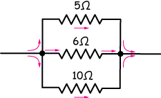
Here are the same three resistors connected in parallel. The current splits into three separate currents at the node on the left, and recombines after passing through the resistors at the node on the right. A node will be any branching point in a circuit – any point where the current can flow in more than one direction.
Kirchhoff's rules
Kirchhoff's rules (Gustav Kirchoff, 1845) are simple rules that help us to do the bookkeeping of currents and potentials in any circuit. There are two.
1. Loop rule (the rule for potentials)
The sum of potential gains in a closed circuit is equal to the sum of potential drops. Another way to say that is the voltage changes around any closed loop must sum to zero.
This rule can be written in summation notation like this:
$$\sum_{i = 1}^n V_i = 0,$$
where n is the number of potential changes (batteries or resistors). Here's a very simple example. This circuit consists of one battery and one resistor. The battery is is a potential source and the resistor represents a potential drop as current traverses the circuit.
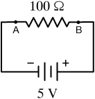
If we measure the potential between points A and B, we're measuring the voltage drop across the 100 Ω resistor and the potential of the battery, so they're both 5 Volts.
The battery raises the potential of electrons, and they lose that potential traversing the resistor.
2. Junction rule (the rule for currents)
The sum of all currents into a junction is the same as the sum of all currents leaving it.
If we define a junction in a circuit as any place where wires split apart or join together, then Kirchhoff's junction rule says that the total current into and out of any junction must be the same. In summation notation, we can write
$$\sum_{i=1}^m I_{in} = \sum_{j=1}^n I_{out},$$
where m is the number of wires on one side of the junction and n is the number on the other. Here it is in a diagram.

On the left, $I_0 = I_1 + I_2 + I_3,$ and on the right $I_1 + I_2 + I_3 = I_0.$ The dark spots are the junctions.
The simplest circuit
The simplest circuit consists of a battery and a resistor connected in series, like this:
Now this circuit doesn't really do much, except maybe heat up the resistor and drain the battery, but you will see that understanding it will be immensely helpful in analyzing much more complicated circuits.
Direction of current
You know that what's moving in electric circuits is electrons, which carry a negative charge. The trick is that the people who first discovered and explored electricity,
including Benjamin Franklin, called the charge of the particle that moves in circuits "positive" (because they didn't know), and we're stuck with it.
In DC circuits, we always assume that what's moving is a positive particle, originating from the positive pole of a battery and terminating (seeking) the negative pole. It's technically wrong, but it turns out not to matter in the least, so I'd get used to it.
Here's that circuit with the proper currents sketched in:

In circuit analysis, we always assume the current to be the movement of positive charges.
Circuit analysis using Ohm's law: $V = IR$
Now let's use Ohm's law, V = IR, to analyze our simple circuit.
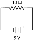
We have a closed circuit with a 10Ω resistor and a 5V battery, so we can rearrange Ohm's law to calculate the current:
$$I = \frac{V}{R} \: \color{#E90F89}{\longrightarrow} \: I = \frac{5 \, V}{10 \, \Omega}$$
and the current is
$$I = 0.5 \, A$$
Now for a little more terminology. We refer to a battery as a potential gain in a circuit, and we say that potential (or voltage) is dropped across a resistor. The sum of the voltage gains minus the sum of the voltage drops in a circuit must be zero. In our circuit, there is a 5V gain and a 5V drop, so we're OK.
answer
We could either reduce the potential (voltage) or increase the resistance.
In a circuit, the sum of the voltage gains must equal the sum of the voltage drops.
A new circuit: resistors in series
Now let's analyze our first circuit with two resistors. For reasons that will become apparent when we're done, this circuit is called a voltage divider. Here's one:
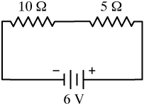
This circuit consists of 10 Ω and 5 Ω resistors wired in series with a 6V battery. When we encounter series resistors like this, we need to find the total resistance, which is just the sum of the two resistors.
$$ \begin{align} R_{tot} &= 10 \, \Omega + 5 \, \Omega \\[5pt] &= 15 \, \Omega \end{align}$$
Resistors in series
The total resistance of n resistors in series is just the sum of all n resistances, or
$$R_{tot} = R_1 + R_2 + R_3 + \dots + R_n.$$
Now we can effectively reduce our two-resistor circuit to an equivalent one-resistor circuit with a 15 Ω resistor and our 6V battery.

Now it's easy to calculate the current through our circuit,
$$I = \frac{V}{R} \phantom{000} I = \frac{6 \, V}{15 \, \Omega}$$
$$I = 0.4 \, A$$
Now that our equivalent circuit has helped us to calculate the current, we need to go back and calculate the potential drops across each resistor.
They are of different sizes, so some part of the total voltage will be dropped across each one. We use Ohm's law in the form V = IR twice:
$$ \begin{align} V &= IR \\[5pt] V_{10} &= (0.4 \, A)(10 \, \Omega) = 4 \, V \\[5pt] V_5 &= (0.4 \, A)( \phantom{0} 5 \, \Omega) = 2 \, V \\[5pt] \hline &\phantom{000000} \color{#E90F89}{\text{total drops:}} \: \: 6 \, V \end{align}$$
So 4 V of our 6 V are dropped across the larger 10 Ω resistor and the other 2 V (it all has to be accounted for) are dropped across the smaller 5 Ω resistor. You might have noticed that the 10 Ω resistor provides ⅔ of the total resistance, and ⅔ of the voltage is dropped across it. Likewise, the 5 Ω resistor is ⅓ of the total resistance, and ⅓ of the 6V potential increase is dropped across it. The voltage drops in such a circuit are always proportional to the fraction of total resistance.
That's everything there is to know about this circuit: We know the current throughout, the voltage gain and all of the voltage drops.
Voltage dividers
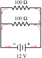
We call the circuit above a voltage divider because it can be used to divide a single potential increase into smaller ones. Imagine you have an electronic device with a 12V battery, but inside of it are two separate circuits, each of which needs a different power source, say 8V and 4V.
The circuit below would get the job done:
The red wires represent volt-meters. Volt meters are capable of determining a potential difference across two points, like pairs A-B and B-C in the voltage divider, without significantly affecting the circuit. If you wanted a 4V potential increase, you'd use points A and B like the terminals of a 4V battery, and if you needed 8V, you'd use points B and C as terminals of an 8V battery. The 100 Ω and 200 Ω resistors could be changed to provide either different voltages or more or less current.

Digital multi-meters
A common tool of real circuit building and analysis is the digital multi-meter. A multi-meter is capable of measuring potential, current, and many other characteristics of both DC and AC circuits. It's a handy tool to have around, whether you're working on sophisticated electronics or wiring your house.
A multi-meter has what we call a high internal impedance or resistance. Because it's resistance is so high, it doesn't really draw too much current from a circuit in order to make its measurements. That's good because you'd like to be judging your circuit on its own merits, not as changed somehow by the meter.
It's a really good idea for you to get to know a multimeter like this one so that you can use it effectively.

More resistors in series
Here's a circuit with three resistors in series. The principles are all the same. Our goal is to
- Find the total resistance and draw and equivalent circuit with just a resistor and a battery
- Use that circuit to calculate the total current
- Use that current with Ohm's law, V = IR, to calculate the voltage drops across all resistors.
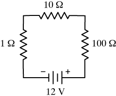
Now the total resistance will be 1Ω + 10Ω + 100Ω = 111Ω. Then we use that resistance to calculate the current, which will be the same throughout this circuit. Before we do that, which resistors will contribute the most and least toward limiting the current in this circuit?
$$I = \frac{V}{R} \: \color{#E90F89}{\longrightarrow} \: I = \frac{12 \, V}{111 \, \Omega}$$
So our current is
$$I = 0.108 \, A \: \: \color{#E90F89}{\text{or}} \: \: 108 \, mA$$
By the way, you should be getting good at recognizing that milli = 1/1000, so 0.108 Amps is 108 mA. Milliamps is a unit used frequently in circuit analysis and other fields.
Now we use that current to find the voltage drops across each resistor, remembering that they should sum to 12V:
$$ \begin{align} V &= IR \\[5pt] V_{100} &= (0.108 \, A)(100 \, \Omega) = 10.8 \, V \\[5pt] V_{10} &= (0.108 \, A)( \phantom{0} 10 \, \Omega) = 1.08 \, V \\[5pt] V_{1} &= (0.108 \, A)( \phantom{00} 1 \, \Omega) = 0.108 \, V \\[5pt] \hline &\phantom{00000000} \color{#E90F89}{\text{total drops:}} \: \: 12 \, V \end{align}$$
You can see that for resistors wired in series, the voltage drop is proportional to the resistance.
The idea of replacing a complicated circuit by a simpler one for the purpose of analysis is used often, and it has a name, Thevenin's theorem. The simpler circuit is often called the Thevenin's equivalent circuit.
Thevenin's theorem
Any circuit consisting of resistors and batteries can be replaced for analysis by a series with a single resistor and a single battery.
A circuit with resistors in parallel
Here is our first example of a simple circuit with two resistors wired not in series but in parallel.
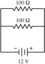
Circuits are often written like this and it's up to you to recognize that they're parallel and analyze them accordingly. But it might be helpful to re-draw such a circuit like this:
Now it's much more plain to see that the two resistors are wired in parallel, and are acting more or less like a single element in the circuit. The current (
Now the total resistance of n resistors wired in parallel is not a simple sum. It is the reciprocal of the sum of reciprocal resistances:
$$R_{tot} = \left( \frac{1}{R_1} + \frac{1}{R_2} + \dots +\frac{1}{R_n} \right)^{-1}$$
More on that later, but the total resistance of our two 100 Ω parallel resistors would be:
$$R_{tot} = \left( \frac{1}{100} + \frac{1}{100} \right)^{-1} = \left( \frac{2}{100} \right)^{-1} = 50 \, \Omega$$
Now that's worth thinking about. The total resistance is less than either of our two resistors. It's because the current gets to split into two branches. Think of it as a garden hose being choked into a narrower section. Now put another of those sections in and, no matter how narrow they are, the flow will improve.
Now we can write an equivalent circuit consisting of a 12 V battery and a 50 Ω resistor:
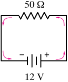
It's easy to analyze this equivalent circuit. The current is I = V/R = 12/50 = 0.24A or 240 mA. The voltage drop across the 50 Ω resistor has to be 12 V because it's the only drop in this circuit, and V = IR = 0.24(50) = 12V.
Now the important thing about resistors in parallel is that the voltage drop across a group of parallel resistors is always the same.
The voltage drop across a group of parallel resistors is the same. Calculate it by finding the total resistance of the parallel resistors, then calculating the voltage drop of the equivalent resistor
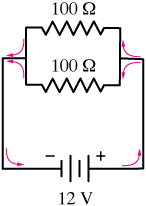
So if we go back to our original circuit,
The voltage drop across each of the 100 Ω resistors is 12V, so we can calculate the current through each resistor. That current will be different from the 240 mA coming from the battery because some goes through each resistor.
In fact, in this case, because the resistances are the same, we'd expect each current to be half of 240 mA or 120 mA, ... but let's calculate it just for drill:
$$ \begin{align} I = \frac{V}{R} \: \color{#E90F89}{\rightarrow} I = \frac{12 \, V}{100 \, \Omega} &= 0.120 \, A \\[5pt] &\text{or} \: \: 120\, mA \end{align}$$
So in this circuit, the current is limited by the resistors to 250 mA. 250 mA of current leaves the battery, divides in half at the first node, with 120 mA passing through each of the 100 Ω resistors. These currents join at the second node to complete the circuit at the battery.
Notice that a simple parallel circuit like this can act as a current divider.
A slightly more complicated parallel circuit
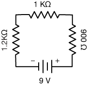
Now let's try a more complicated parallel-resistor circuit. This one has three resistors with different resistances.

Once again, it might be useful, at least for now, to re-visualize this circuit like this so you can see that those three resistors are in parallel, and that the current will split between them (though un-equally this time).

The first thing we do is to calculate the total resistance. Using the parallel resistor equation, we have
$$R_{tot} = \left( \frac{1}{1} + \frac{1}{10} + \frac{1}{100} \right)^{-1}$$
We can solve this easily by hand by taking 100 as the common denominator to get
$$ \begin{align} R_tot &= \left( \frac{100 + 10 + 1}{100} \right)^{-1} = \left( \right)^{-1} \\[5pt] &= \frac{100}{111} = 0.9009 \, \Omega \end{align}$$
Finally, we ought to note that we don't really know any of those resistance values well enough to express the total resistance to the 10,000ths place, so we should just round it to
$$R_{tot} \approx 0.9 \, \Omega$$
Now we have our equivalent circuit:

We use it for two things. First we note that the voltage drop across the 0.9 Ω resistor has to be 12V (and therefore the voltage drop across all three parallel resistors is 12 V), and second, we calculate the current through the battery: I = V/R = 12V / 0.9 Ω = 13.3 A.
Now we can go back to our original circuit and calculate the currents through each of the parallel resistors. First, we should think about what to expect: The most current should flow through the 1Ω resistor, the least through the 100 Ω resistor. We'll call the currents I1, I10 and I100, respectively.
The calculations are:
$$ \begin{align} I_1 = \frac{V}{R_1} \; \color{#E90F89}{\rightarrow} \; I_1 = \frac{12 \, V}{1 \, \Omega} &= 12 \, A \\[5pt] I_{10} = \frac{V}{R_{10}} \; \color{#E90F89}{\rightarrow} \; I_{10} = \frac{12 \, V}{10 \, \Omega} &= 1.2 \, A \\[5pt] I_{100} = \frac{V}{R_{100}} \; \color{#E90F89}{\rightarrow} \; I_{100} = \frac{12 \, V}{100 \, \Omega} &= 0.12 \, A \\[5pt] \hline \color{#E90F89}{\text{total current: }} &\: \: 13.3 \, A \end{align}$$
Notice that the current, 13.3 A, calculated this way is the same as that which we calculated using the total resistance. These circuits are satisfying because when you've got everything right, it's all self-consistent.
In this circuit, most of the current passes through the 1 Ω resistor, as we expected, and very little passes through the 100 Ω one.
OK, so that's it for very basic series and parallel resistor-battery circuits. Here is a summary of the steps we took to analyze these circuits:
Steps for analyzing simple circuits
![]()
-
Calculate the total resistance:
$$R_{tot} = R_1 + R_2 + R_3 + \dots$$
-
Calculate the current in the equivalent circuit:
$$I = \frac{V}{R}$$
-
Use the total current to calculate the voltage drop across each resistor: $$V = IR$$
- In a series circuit, the current is the same through all resistors.
![]()
-
Calculate the total resistance:
$$R_{tot} = \left( \frac{1}{R_1} + \frac{1}{R_2} + \frac{1}{R_3} + \dots \right)^{-1}$$
-
Calculate the current in the equivalent circuit:
$$I = \frac{V}{R}$$
-
The voltage drop across parallel resistors is the same across all of them.
-
Calculate the current through each of the parallel resistors.
$$I = \frac{V}{R}$$
In the next section we'll look at resistor-battery circuits with a mix of series and parallel resistors. They're a little more complicated, but if you take the time to master the problems below, you shouldn't have any problem making the leap.
Practice circuits
Solve for all voltage drops and currents everywhere in these DC circuits:
-

Solution
Calculate the current using Ohm's law:
$$V = IR \color{magenta}{\longrightarrow} I = \frac{V}{R}$$
$$ \begin{align} I = \frac{V}{R} &= \frac{5 \, V}{400 \, \Omega} \\[5pt] &= 0.00125 \, A \: \bf{ = 1.25 \, mA} \end{align}$$
Notice that we try to express our answers in units that give numbers that are around what we could count on our fingers. Milliamps (mA) works here.
-
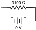
Solution
First we need to reduce those three series resistors to one:
$$ \begin{align} R_{tot} &= 1200 + 1000 + 900 \\[5pt] &= 3100 \, \Omega \end{align}$$
Don't forget to convert KΩ to Ohms. That gives us the equivalent circuit:
Now we have the total current:
$$I = \frac{V}{R} = \frac{9 \, V}{3100 \, \Omega} = 0.0029 \, A$$
Now we can use that current to calculate the voltage drops across each resistor:
$$ \begin{align} V_{1200} &= IR = (0.0029 \, A)(1200 \, \Omega) = 3.48 \, V \\[5pt] V_{1000} &= (0.0029 \, A)(1000 \, \Omega) = 2.90 \, V \\[5pt] V_{900} &= (0.0029 \, A)(900 \, \Omega) = 2.61 \, V \end{align}$$
Those voltage drops sum to 8.99 V. The small loss is due to round off errors in the above calculations. You might want to use more digits in the middle of your calculations, then round off at the very end.
-
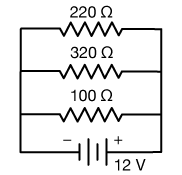
Solution
First we need to reduce those three parallel resistors to one:
$$ \begin{align} R_{tot} &= \left( \frac{1}{220} + \frac{1}{320} + \frac{1}{100} \right)^{-1} \\[5pt] &= (0.01767)^{-1} \\[5pt] &= \bf{56.59 \, \Omega} \end{align}$$
That gives us the equivalent circuit:
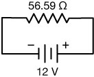
Now the total current is
$$I = \frac{V}{R} = \frac{12 \, V}{56.59 \, \Omega} = 0.212 \, A$$
Each of the parallel resistors in the original circut shares the same 12V drop, so we can calculate the current through each like this:
$$ \begin{align} I_{220} = \frac{V}{R} &= \frac{12 \, V}{220 \, \Omega} = 0.0545 \, A \\[5pt] I_{320} &= \frac{12 \, V}{320 \, \Omega} = 0.0375 \, A \\[5pt] I_{100} &= \frac{12 \, V}{100 \, \Omega} = 0.120 \, A \end{align}$$
These currents sum to our total current, so we know everything we need to know about this circuit. Notice that more current flows through the weakest resistor, just what we'd expect.
-
Solution
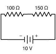
First we need to reduce those two series resistors to one:
$$R_{tot} = 100 + 150 = 250 \, \Omega$$
That gives us the equivalent circuit:

Now we have the total current:
$$I = \frac{V}{R} = \frac{10 \, V}{250 \, \Omega} = 0.040 \, A$$
Now we can use that current to calculate the voltage drops across each resistor:
$$ \begin{align} V &= IR \\[5pt] V_{100} &= (0.040 \, A)(100 \, \Omega) = 4 \, V \\[5pt] V_{150} &= (0.040 \, A)(150 \, \Omega) = 6 \, V \end{align}$$
Those voltage drops sum to our total voltage increas of 10 V.
-

Solution
First we need to reduce those two parallel resistors to one:
$$ \begin{align} R_{tot} &= \left( \frac{1}{100} + \frac{1}{300} \right)^{-1} \\[5pt] &= (0.01333)^{-1} \\[5pt] &= 75 \, \Omega \end{align}$$
That gives us the equivalent circuit:
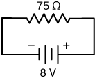
Now the total current is
$$I = \frac{V}{R} = \frac{9 \, V}{75 \, \Omega} = 0.1067 \, A$$
Each of the parallel resistors in the original circut shares the same 8V drop, so we can calculate the current through each like this:
$$ \begin{align} I_{100} = \frac{V}{R} &= \frac{8 \, V}{100 \, \Omega} = 0.08 \, A \\[5pt] I_{300} &= \frac{8 \, V}{300 \, \Omega} = 0.027 \, A \end{align}$$
These currents sum to our total current, plus or minus some roundoff error. Notice that more current flows through the weakest resistor, just what we'd expect.
-
Solution
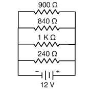
First we need to reduce those four parallel resistors to one:
$$ \begin{align} R_{tot} &= \left( \frac{1}{900} + \frac{1}{840} + \frac{1}{1000} + \frac{1}{240} \right)^{-1} \\[5pt] &= (0.007468)^{-1} \\[5pt] &= \bf{133.9 \, \Omega} \end{align}$$
That gives us the equivalent circuit:
Now the total current is
$$I = \frac{V}{R} = \frac{12 \, V}{133.9 \, \Omega} = 0.0896 \, A$$
Each of the parallel resistors in the original circut shares the same 12V drop, so we can calculate the current through each like this:
$$ \begin{align} I_{900} = \frac{V}{R} &= \frac{12 \, V}{900 \, \Omega} = 0.0133 \, A \\[5pt] I_{840} &= \frac{12 \, V}{840 \, \Omega} = 0.0143 \, A \\[5pt] I_{1K} &= \frac{12 \, V}{1000 \, \Omega} = 0.0120 \, A \\[5pt] I_{240} &= \frac{12 \, V}{240 \, \Omega} = 0.0500 \, A \end{align}$$
These currents sum to our total current. Notice that more current flows through the weakest resistor, just what we'd expect.

Electric potential
Review potential ("voltage;") and Ohm's law here.
Circuits 2
Move on to more complicated electric circuits.


![]()
xaktly.com by Dr. Jeff Cruzan is licensed under a Creative Commons Attribution-NonCommercial-ShareAlike 3.0 Unported License. © 2021-2025, Jeff Cruzan. All text and images on this website not specifically attributed to another source were created by me and I reserve all rights as to their use. Any opinions expressed on this website are entirely mine, and do not necessarily reflect the views of any of my employers. Please feel free to send any questions or comments to jeff.cruzan@verizon.net.